
What is counter
A
counter may be a digital circuit or device that counts the amount of products
and returns predefined values supported clock pulse applications. The output of
the counter are often wont to count the amount of pulses. The counter circuit
is typically composed of several flip-flops connected within the cascade
method. Counter automation and digitally based components are very widely used
components.
Micro controller applications require
external events or precise internal time delay generation and calculation of
pulse frequency as required . These phenomena are often utilized in digital
systems and automation. Both of those events are often performed by software techniques,
but software loops for counting won't give accurate results, as little more
important work isn't done. These problems are often corrected by timers and
counters in micro controllers that are used as interrupts.
Classification of counters
In
digital circuits, counters are often implemented using register-type circuits
like flip-flops,
The counters are classified as
given below.
Asynchronous
or Ripple Counter - Sequence state flip-flops are used as clocks
to define the Ripple Counter because the Replay Counter State. additionally ,
asynchronous counters are less useful than synchronous counters in complex,
high-frequency systems.
Synchronous
Counter - A synchronous counter has an indoor clock,
while asynchronous counters don't . As a result, all flip-flops during a
synchronous counter run simultaneously by one , normal clock pulse. (All state
bits are converted to one clock control)
Plc counter
The PLC counter may be a function
block that counts until or below a given threshold. Now-a-days PSC may be a
tool widely utilized in industrial automation. PLC counters also are utilized
in SCADA systems by calculating allocated act . once you are allocating a task,
counters widely utilized in PLC programming to count what percentage times a
process has been completed. Or what percentage products are produced.
How to address a counter in PLC
Counters
use variables of some data types to store numbers during a PLC. All counters
are required to store a minimum of two numbers, these two numbers are saved
during a fixed data type, which also has their limitations. Many PLCs save
these two numbers as WORD or Integer data types.
Below shown addressing for the PLC
UP Counter: this is often wont to
indicate when a count has reached the utmost 'up count' value.
Input
Signal
|
Data type
|
Description
|
EN
|
BOOL
|
Enables block operation
|
R
|
BOOL
|
Reset CV
|
PV
|
UINT, UDINT
|
Preset value of the up counter
|
Signal
|
Data type
|
Description
|
ENO
|
BOOL
|
Indicates completion of operation
|
CV
|
UINT, UDINT
|
Current value of the up counter
|


Signal
|
Data type
|
Description
|
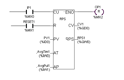
CU
|
BOOL
|
Pulse input - Count Up
|
R
|
BOOL
|
Reset CV
|
PV
|
UDINT
|
Preset value of the Up counter
|
AT
|
UINT
|
Averaging time for RPS update in 0.1s resolution (0.1 to 6553.5s)
|
AP
|
UINT
|
Average number of Pulses for RPS update (1 to 65535)
|
Signal
|
Data type
|
Description
|
ENO
|
BOOL
|
Set when CV >= PV
|
CV
|
UDINT
|
Current value of the Up counter
|
RPS
|
UINT
|
Calculated RPS value in 0.01Hz resolution (0.01Hz to200Hz)*
|
AT
|
AP
|
RPS Output Calculated & Updated
|
> 0
|
= 0
|
every 'Average Time'
|
= 0
|
> 0
|
when No of input pulses >= 'Average Pulses'
|
> 0
|
> 0
|
condition that satisfies first (as per above 2 steps)
|
= 0
|
= 0
|
every input pulse
|
Input
|
Output
|
Update time (sec)
|
||
Input Pulse @ CU
|
AT (sec)
|
AP
|
RPS output (Hz)
|
|
10 Hz
|
0
|
50
|
10.00
|
5
|
20 Hz
|
0
|
50
|
20
|
2.5
|
25 Hz
|
1.5
|
0
|
25.00
|
1.5
|
30 Hz
|
2.0
|
80
|
30.00
|
2
|
100Hz
|
2.0
|
80
|
100
|
0.8
|
50 Hz
|
0
|
0
|
50.00
|
Every pulse (20ms)
|


Signal
|
Data type
|
Description
|
CU
|
BOOL
|
Count Up
|
CD
|
BOOL
|
Count Down
|
R
|
BOOL
|
Reset CV
|
LD
|
BOOL
|
Used to set CV with PV
|
PV
|
INT, DINT
|
Preset value of counter
|
Signal
|
Data type
|
Description
|
QU
|
BOOL
|
set when CV >= PV
|
QD
|
BOOL
|
set when CV <= 0
|
CV
|
INT, DINT
|
Current value of counter
|


Signal
|
Data type
|
Description
|
EN
|
BOOL
|
Enables block operation
|
R
|
BOOL
|
Reset CV
|
PV
|
UINT, UDINT
|
Preset value of the down counter
|
Signal
|
Data type
|
Description
|
ENO
|
BOOL
|
Indicates completion of operation
|
CV
|
UINT, UDINT
|
Current value of the down counter
|


All counters are supported different
applications in industry. Plc counter avoid the external expenses of shopping
for a counter. In plc counter is inbuilt so got to connect External counter to automatic counts.
Note:
1. once you are communicating the plc
online or offline you want to give the right address for a input & output.
Every input & Output define in Boolean expression only
2. All the function block define
consistent with there application so it's going to be integer,Double Integer,
Word or Double Words. All the counters Preset and cv value expressed in Int or
Double int.
1. A counter may be a PLC instruction
that either Increment(counts up) or decrements (counts down) an integer number
value when actuate by the passage a touch from 0 to 1 (“false” to “true”).
Counter instructions are available three basic types: up counters, down
counters, and up/down counters.
Uses Of Counters
1. Counters are often utilized in
industries for time delays and production monitoring.
2. Cement manufacturing.
3. Paper industry etc…
Comments
Post a Comment
If you have any Doubts plz let me know